
 424 364 2640
How it Works
- Reduction I2R Losses, improving Power Factor
- Reduction Core Losses in inductive Loads.
- Reduction of electric usage by monitoring the power consumption.
- Reduction of electric breakdown and Surge Suppression
- Reduction in carbon emission.
Reduced I2R Losses
- Current (Amps) dissipates in the form of Heat in distribution network, Electrical wiring and wire Windings inside transformer and switch gear.
- By Improving power factor current can be reduced to minimum, Accordingly reduction in the losses.
- Note: if the current is reduced to half, losses reduce 4 times as per the following formula.
Power Loss = I2R = Amps2 x Resistance
Thus ampere reduction account for low electricity bills.
Reduced Core Losses
Electrical Energy is converted to Mechanical power by using magnetic core and alternating current passing through magnet wire wound around the core.
Example as shownn in figure below:
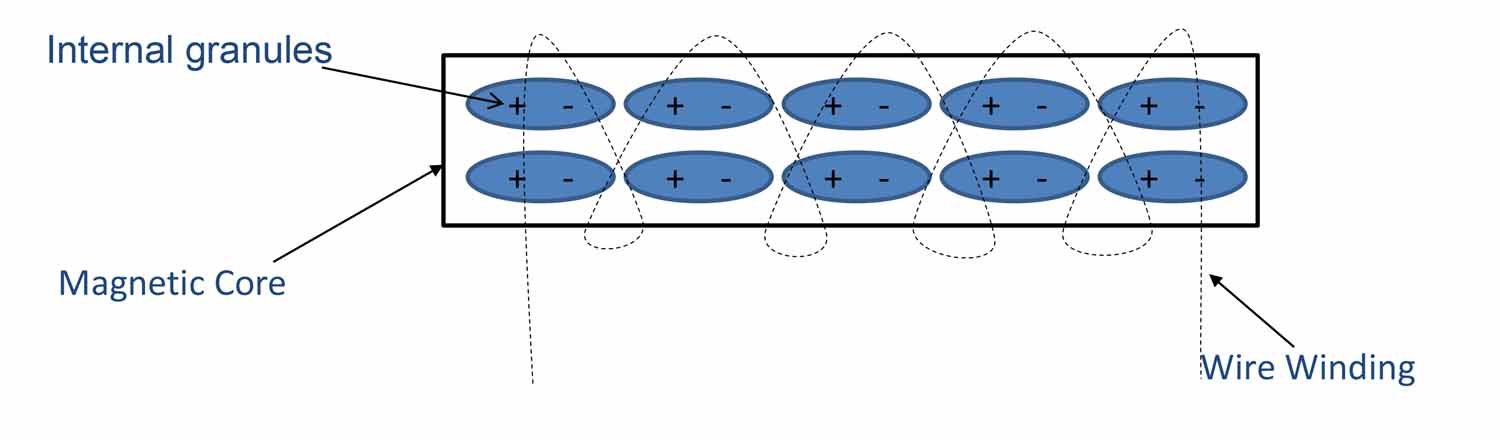
When no Current passes through the Magnet wire the internal granules(Dipole) of magnetic core are stationary. CRGO ( Cold Rolled Grain Oriented) .
When AC current passes through the magnet wire the internal grains(Dipole) in the magnetic core rotate as per the alternating current.
Example as shownn in figure below:
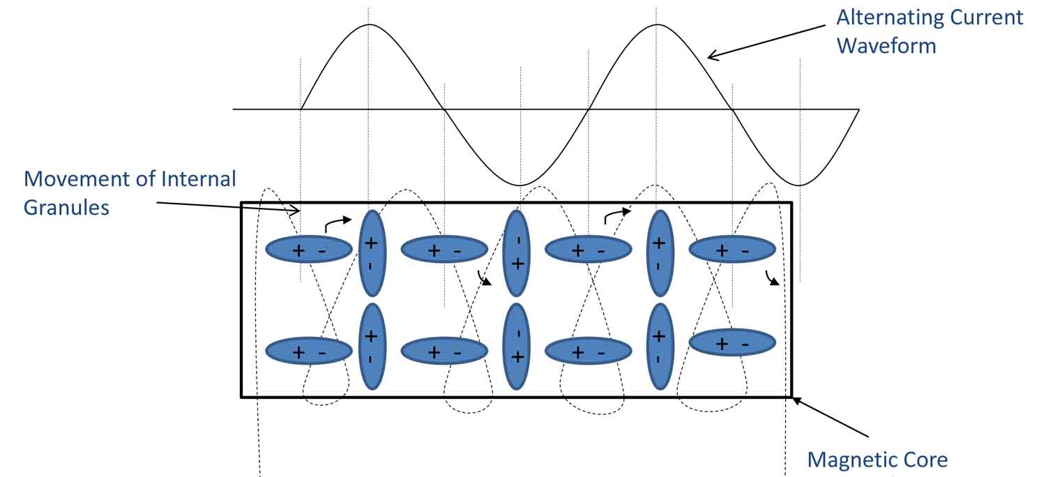
There are losses generated like core loss, hysteresis loss, Eddy Current loss in magnetic core and dissipated in the form of heat. The magnetic core is designed for 50Hz the movement of grains is same as 50Hz voltage waveform.
If any distortion arise in mains voltage waveform, magnetic core respond to distortion by producing extra heat as the grains movement does not change abruptly but tend to move at primary frequency 50Hz. Any distortion in the voltage is converted to heat in core .
For distortion or high frequency on voltage waveform, capacitors provides low impedance path and reduce the distortion maintain the voltage waveform and reduced core losses achieved.
Reduced electric usage by monitoring the power consumption
LCD monitor Display shows all electrical Parameters which correspond to power usage. Usually installed near to mains distribution Board so consumer can check usage and manage the power requirement. Consumers can save another 10-15% just by changing the consumption pattern and habits by monitoring the power consumption.
Reduced electric breakdown & Surge Suppression
Capacitor bank work as surge suppressor
where energy can be calculated by following formula
Energy = ½ CV2
Energy is joule(J)
Capacitance is microfarad (uf)
Voltage is Volt (V).
Capacitors are tested upto 2000V and maximum short circuit capacity at 10,000Amps.
The minimum capacitor of 5 uf = 10 joules
Energy(J) = ½ x 5 x 10-6 x (2000) = 10 joules
In the model ES-1
capacity range of capacitor bank is from 5 uf to 155 uf
surge suppression capacity is from 10 joule to 310 joules.
Reduced Carbon Emission
Power saving lead to Reduced Carbon footprints.
This can be calculated by standard formula for calculation of CO2 emissions from DECC’s organisation.
kWh x Conversion Factor = CO2 in Kgs.
Conversion factor of Electricity is 0.69
For Example, if there is a saving of 1000 units of electricity per month
then carbon emission reduced 1000 x 0.69 = 690 Kg / Month
THANK YOU
Advantages for Consumer
- Reduction I2R Losses, improving Power Factor
- Reduction Core Losses in inductive Loads.
- Reduction of electric usage by monitoring the power consumption.
- Reduction of electric breakdown due to Surge Suppression
- Reduction in carbon emission.
Reduced I2R Losses
- Current (Amps) dissipates in the form of Heat in distribution network, Electrical wiring and wire Windings inside transformer and switchgear.
- By Improving power factor current can be reduced to minimum, Accordingly reduction in the losses.
- Note: if the current is reduced to half, losses reduce 4 times as per the following formula.
Power Loss = I2R = Amps2 x Resistance
Thus ampere reduction account for low electricity bills.
Reduced Core Losses
Electrical Energy is converted to Mechanical power by using magnetic core and alternating current passing through magnet wire wound around the core.
Example as shown in figure below.
When no Current passes through the Magnet wire the internal granules(Dipole) of magnetic core are stationary. CRGO ( Cold Rolled Grain Oriented) .
When AC current passes through the magnet wire the internal grains(Dipole) in the magnetic core rotate as per the alternating current. As shown below.
There are losses generated like core loss, hysteresis loss, Eddy Current loss in magnetic core and dissipated in the form of heat. The magnetic core is designed for 50Hz the movement of grains is same as 50Hz voltage waveform.
If any distortion arise in mains voltage waveform, magnetic core respond to distortion by producing extra heat as the grains movement does not change abruptly but tend to move at primary frequency 50Hz. Any distortion in the voltage is converted to heat in core .
For distortion or high frequency on voltage waveform, capacitors provides low impedance path and reduce the distortion maintain the voltage waveform and reduced core losses achieved.
Reduced electric usage by monitoring the power consumption
LCD monitor Display shows all electrical Parameters which correspond to power usage. Usually installed near to mains distribution Board so consumer can check usage and manage the power requirement. Consumers can save another 10-15% just by changing the consumption pattern and habits by monitoring the power consumption.
Reduced electric breakdown & Surge Suppression
Capacitor bank work as surge suppressor
where energy can be calculated by following formula
Energy = ½ CV2
Energy is joule(J)
Capacitance is microfarad (uf)
Voltage is Volt (V).
Capacitors are tested upto 2000V and maximum short circuit capacity at 10,000Amps.
The minimum capacitor of 5 uf = 10 joules
Energy(J) = ½ x 5 x 10-6 x (2000) = 10 joules
In the model ES-1
capacity range of capacitor bank is from 5 uf to 155 uf
surge suppression capacity is from 10 joule to 310 joules.
Reduced Carbon Emission
Power saving lead to Reduced Carbon footprints.
This can be calculated by standard formula for calculation of CO2 emissions from DECC’s organisation.
kWh x Conversion Factor = CO2 in Kgs.
Conversion factor of Electricity is 0.69
For Example, if there is a saving of 1000 units of electricity per month
then carbon emission reduced 1000 x 0.69 = 690 Kg / Month
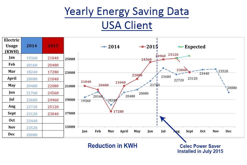
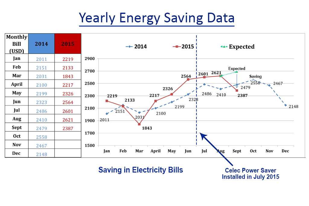
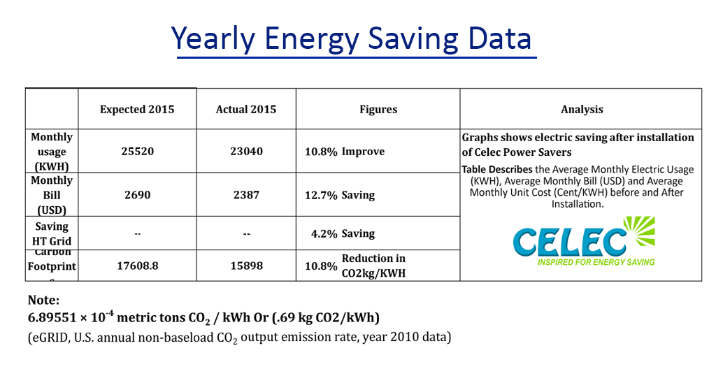
Yearly Energy Saving Data USA client

Yearly Energy Saving Data USA

Yearly Energy Saving Data USA

THANK YOU